![]()
The aim of this project is to implement driver functionality for the ethernet interface in the ETRAX unit. This project is finished when the server can receive and transmit ethernet packets. A stub is provided which recognises ping-requests, ICMP echo requests, and answers them with ICMP echo replies in order to allow tests of the solution. The stub is responsible for Logical Link Control, LLC.
Since there is quite a lot of non-trivial hardware related programming involved in this project, a large part of the source code is provided as a skeleton. There is some administration in order to obtain the source code. Refer to the suggested design of the class hierarchy as well as advice on how to approach the completion of the skeleton code. An executable which may be loaded into the ETRAX unit is compiled, linked, and loaded in the same manner as in the previous overview of the system.
Read chapter 1, the introduction, and 2, the link layer, as well as chapters 6 and 7, about ICMP and the ping program in Steven's book. An ethernet frame description is presented in p.23.
Learn more about the ETRAX buffer structure and read the ETRAX designers reference, pp.41-46. Read about the ETRAX receive and transmit buffers in the lecture notes on ETRAX pp.22-29.
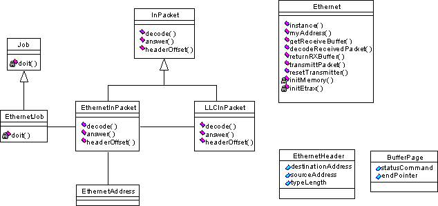
All levels of the protocol-stack will be designed according to the same pattern. Each level is described by a derived class of the base class InPacket. The derived class is implemented in order to decode its level. An inherited answer method from InPacket is to be used to send an answer back to the frame where the derived class instance was created. The decoding of an Address Resolution Protocol, ARP, packet is described below

Assume that the LLC level has detected an ARP-packet, as
shown above. The packet is decoded and generates an answer
according to the source code in the files below.
llc.cc
void
llcInPacket::decode()
{
...
// Its an ARP packet of some sort
ARPInPacket* anARPPacket = new ARPInPacket(myData + llcHeaderLength,
myLength - llcHeaderLength,
this,
myFrameType);
anARPPacket->decode();
...
}
arp.cc
ARPInPacket::ARPInPacket(byte* theData,
udword theLength,
InPacket* theFrame,
uword theTypeLen):
InPacket(theData,theLength,theFrame),
myFrameType(theTypeLen)
{
}void
ARPInPacket::decode()
{
...
myFrame->answer(someData, someLength);
}
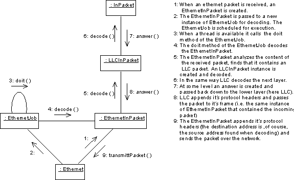
From these fragments of source code it is clear that
In the suggested design there are two complete class implementations to be written
The header file ethernet.hh contains the class declarations with comments on the functionality required in the methods. In addition, the following methods require some work

Follow the details of the implementation by opening the files ethernet.hh and ethernet.cc in an editor. To start with, the C-function ethernet_interrupt() is called from the operating system when an external packet interrupt is recieved. The assembly code may be found in the file osys_etr.s. The function ethernet_interrupt() has four different handles depending on the type of interrupt received,
The handle of interest here is the one in response to a packet received interrupt, Ethernet::getReceiveBuffer(), which is responsible of determining the position of an available packet in the in-buffer. The packet must be handled in a different manner when it begins at the end of the physical buffer space and wraps around and ends at the beginning of the physical buffer memory, compared to when it is located in consecutive memory space. Make sure you understand the need for the pointers data1 and data2, and the length variables lenght1 and length2.
The handle returns a boolean informing the interrupt-context function whether a packet is available. A message is then sent to the thread thread_main() if a packet is available and ready for processing. The response to the message is the method Ethernet::decodeReceivedPacket() which creates an instance of EthernetInPacket, and schedules a new EthernetJob in order to handle the available packet. The job will apply its doit() method in order to decode the packet.
The method Ethernet::getReceiveBuffer() might need some further explanation. In the figure below, a packet has been received by the ETRAX unit. The packet occupies the entire first page in the receive buffer and also extends into page two. The pointer endPointer is referencing the first byte after the checksum of the packet. A corresponding design is used in the case where packets are sent from the transmit buffer. A lot may be learnt about receival from a comparison with the solution in the method Ethernet::transmittPacket().
When a packet is beginning at the end of the receive buffer, it might end at the beginning of the buffer. In the case of a buffer wrap, the pointer data1 is set to refer to the first half of the packet and length1 holds the length of the first half of the packet. The pointer data2 is set to refer to the second half of the packet at the beginning of the receive buffer, with length2 telling how long the second half of the packet is. A wrapped packet must be copied into consecutive memory space before it is dispatched to the method Ethernet::decodeReceivedPacket().

The class EthernetHeader is declared to contain exactly the same data fields as those present in an ethernet frame header. When information needs to be extracted from or introduced in the header, a cast is used,
byte* data;
// data is a pointer to a packet in the receive buffer
EthernetHeader* aHeader = (EthernetHeader*)data;
// the data pointer is cast into a pointer to an EthernetHeader
which allows access to information, e.g. the ethernet address of the source, in the ethernet header by the pointer aHeader
EthernetAddress hisNodeAddress = aHeader->sourceAddress;
Throughout the course, the casting will be used according to the example in order to decode the content of all packets.
The type/length field in the ethernet frame header has the
opposite endian
representation compared with the implementation in the ETRAX
unit. Translation between big and little endian is explained by
the example
uword myTypeLen = ((aHeader->typeLen
& 0x00ff) << 8) |
(aHeader->typeLen & 0xff00) >> 8));
Make sure that your present working directory is ~/kurs/src. Remove the subfolder lab2 if it exists in ~/kurs/src. Then, copy all files from your solution in project 1 with the command
cp -r lab1 lab2
and change your present working directory into ~/kurs/src/lab2. Add the skeleton to your previous files with the command
cp -r ~inin/kurs/src/lab2/* .
There should be six files in addition to the ones from project 1 in the directory lab2,
The target of the make process is defined in the file /kurs/make/lab2/modules. Remember to add all the new .cc files into the files file! Make sure your present working directory is ~/kurs/make and type the commands:
The ping-command is used in order to test the implementation of the network interface layer of your solution. There are a few things missing in the server implementation at present. Thus, some temporary information must be entered in order to provide the ping-program with necessary addresses. There are two alternate tests senarios.
1. Using linus.
/sbin/arp -s <ETRAX IP-address> <ETRAX ethernet address> tempE.g., /sbin/arp -s 194.47.61.123 00:67:01:04:02:37 temp, where your parameters should be used,
ping <ETRAX IP-address>which may be terminated by Ctrl-C, and,
/sbin/arp -d <ETRAX IP-address>The entire ARP-cache is shown by the command /sbin/arp -a.
2. Using a command prompt window on your PC
arp -s <ETRAX IP-address> <ETRAX ethernet address> tempE.g. arp -s 194.47.61.123 00-67-01-04-02-37, where your parameters should be used, and
ping <ETRAX IP-address>which may be terminated by
Delete.
The ping-program has an option -s which sets the packet size to be transmitted. Try sending packets with various sizes from 4 to 1450 and make sure you understand which packet sizes are critical.