| AVR Libc Home Page |  |
AVR Libc Development Pages | |||
| Main Page | User Manual | Library Reference | FAQ | Alphabetical Index | Example Projects |
| AVR Libc Home Page | |
AVR Libc Development Pages | |||
| Main Page | User Manual | Library Reference | FAQ | Alphabetical Index | Example Projects |
Makefile can be configured.PWM) to ramp an LED on and off every two seconds. An AT90S2313 processor will be used as the controller. The circuit for this demonstration is shown in the schematic diagram. If you have a development kit, you should be able to use it, rather than build the circuit, for this project.
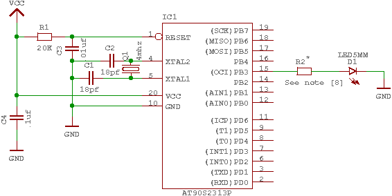
Schematic of circuit for demo project
The source code is given in demo.c. For the sake of this example, create a file called demo.c containing this source code. Some of the more important parts of the code are:
iocompat.h tries to abstract between all this differences using some preprocessor #ifdef statements, so the actual program itself can operate on a common set of symbolic names. The macros defined by that file are:OCR the name of the OCR register used to control the PWM (usually either OCR1 or OCR1A)DDROC the name of the DDR (data direction register) for the OC outputOC1 the pin number of the OC1[A] output within its portTIMER1_TOP the TOP value of the timer used for the PWM (1023 for 10-bit PWMs, 255 for devices that can only handle an 8-bit PWM)TIMER1_PWM_INIT the initialization bits to be set into control register 1A in order to setup 10-bit (or 8-bit) phase and frequency correct PWM modeTIMER1_CLOCKSOURCE the clock bits to set in the respective control register to start the PWM timer; usually the timer runs at full CPU clock for 10-bit PWMs, while it runs on a prescaled clock for 8-bit PWMs
PWM is being used in 10-bit mode, so we need a 16-bit variable to remember the current value.PWM.PWM register. Since we are in an interrupt routine, it is safe to use a 16-bit assignment to the register. Outside of an interrupt, the assignment should only be performed with interrupts disabled if there's a chance that an interrupt routine could also access this register (or another register that uses TEMP), see the appropriate FAQ entry.PWM and enables interrupts.sleep_mode() puts the processor on sleep until the next interrupt, to conserve power. Of course, that probably won't be noticable as we are still driving a LED, it is merely mentioned here to demonstrate the basic principle./* * ---------------------------------------------------------------------------- * "THE BEER-WARE LICENSE" (Revision 42): * <joerg@FreeBSD.ORG> wrote this file. As long as you retain this notice you * can do whatever you want with this stuff. If we meet some day, and you think * this stuff is worth it, you can buy me a beer in return. Joerg Wunsch * ---------------------------------------------------------------------------- * * Simple AVR demonstration. Controls a LED that can be directly * connected from OC1/OC1A to GND. The brightness of the LED is * controlled with the PWM. After each period of the PWM, the PWM * value is either incremented or decremented, that's all. * * $Id: demo.c,v 1.9 2006/01/05 21:30:10 joerg_wunsch Exp $ */ #include <inttypes.h> #include <avr/io.h> #include <avr/interrupt.h> #include <avr/sleep.h> #include "iocompat.h" /* Note [1] */ enum { UP, DOWN }; ISR (TIMER1_OVF_vect) /* Note [2] */ { static uint16_t pwm; /* Note [3] */ static uint8_t direction; switch (direction) /* Note [4] */ { case UP: if (++pwm == TIMER1_TOP) direction = DOWN; break; case DOWN: if (--pwm == 0) direction = UP; break; } OCR = pwm; /* Note [5] */ } void ioinit (void) /* Note [6] */ { /* Timer 1 is 10-bit PWM (8-bit PWM on some ATtinys). */ TCCR1A = TIMER1_PWM_INIT; /* * Start timer 1. * * NB: TCCR1A and TCCR1B could actually be the same register, so * take care to not clobber it. */ TCCR1B |= TIMER1_CLOCKSOURCE; /* * Run any device-dependent timer 1 setup hook if present. */ #if defined(TIMER1_SETUP_HOOK) TIMER1_SETUP_HOOK(); #endif /* Set PWM value to 0. */ OCR = 0; /* Enable OC1 as output. */ DDROC = _BV (OC1); /* Enable timer 1 overflow interrupt. */ TIMSK = _BV (TOIE1); sei (); } int main (void) { ioinit (); /* loop forever, the interrupts are doing the rest */ for (;;) /* Note [7] */ sleep_mode(); return (0); }
-mmcu option is specified. The -Os option will tell the compiler to optimize the code for efficient space usage (at the possible expense of code execution speed). The -g is used to embed debug info. The debug info is useful for disassemblies and doesn't end up in the -c tells the compiler to compile and stop -- don't link. This demo is small enough that we could compile and link in one step. However, real-world projects will have several modules and will typically need to break up the building of the project into several compiles and one link.
$ avr-gcc -g -Os -mmcu=atmega8 -c demo.c
The compilation will create a demo.o file. Next we link it into a binary called demo.elf.
$ avr-gcc -g -mmcu=atmega8 -o demo.elf demo.o
It is important to specify the MCU type when linking. The compiler uses the -mmcu option to choose start-up files and run-time libraries that get linked together. If this option isn't specified, the compiler defaults to the 8515 processor environment, which is most certainly what you didn't want.
Now we have a binary file. Can we do anything useful with it (besides put it into the processor?) The GNU Binutils suite is made up of many useful tools for manipulating object files that get generated. One tool is avr-objdump, which takes information from the object file and displays it in many useful ways. Typing the command by itself will cause it to list out its options.
For instance, to get a feel of the application's size, the -h option can be used. The output of this option shows how much space is used in each of the sections (the .stab and .stabstr sections hold the debugging information and won't make it into the ROM file).
An even more useful option is -S. This option disassembles the binary file and intersperses the source code in the output! This method is much better, in my opinion, than using the -S with the compiler because this listing includes routines from the libraries and the vector table contents. Also, all the "fix-ups" have been satisfied. In other words, the listing generated by this option reflects the actual code that the processor will run.
$ avr-objdump -h -S demo.elf > demo.lst
Here's the output as saved in the demo.lst file:
demo.elf:     file format elf32-avr

Sections:
Idx Name          Size      VMA       LMA       File off  Algn
  0 .text         000000fa  00000000  00000000  00000074  2**1
                  CONTENTS, ALLOC, LOAD, READONLY, CODE
  1 .bss          00000003  00800060  00800060  0000016e  2**0
                  ALLOC
  2 .debug_aranges 00000020  00000000  00000000  0000016e  2**0
                  CONTENTS, READONLY, DEBUGGING
  3 .debug_pubnames 00000035  00000000  00000000  0000018e  2**0
                  CONTENTS, READONLY, DEBUGGING
  4 .debug_info   000000ef  00000000  00000000  000001c3  2**0
                  CONTENTS, READONLY, DEBUGGING
  5 .debug_abbrev 000000b7  00000000  00000000  000002b2  2**0
                  CONTENTS, READONLY, DEBUGGING
  6 .debug_line   0000011a  00000000  00000000  00000369  2**0
                  CONTENTS, READONLY, DEBUGGING
  7 .debug_frame  00000040  00000000  00000000  00000484  2**2
                  CONTENTS, READONLY, DEBUGGING
  8 .debug_str    000000ab  00000000  00000000  000004c4  2**0
                  CONTENTS, READONLY, DEBUGGING

Disassembly of section .text:

00000000 <__vectors>:
   0:	12 c0       	rjmp	.+36     	; 0x26 <__ctors_end>
   2:	76 c0       	rjmp	.+236    	; 0xf0 <__bad_interrupt>
   4:	75 c0       	rjmp	.+234    	; 0xf0 <__bad_interrupt>
   6:	74 c0       	rjmp	.+232    	; 0xf0 <__bad_interrupt>
   8:	73 c0       	rjmp	.+230    	; 0xf0 <__bad_interrupt>
   a:	72 c0       	rjmp	.+228    	; 0xf0 <__bad_interrupt>
   c:	71 c0       	rjmp	.+226    	; 0xf0 <__bad_interrupt>
   e:	70 c0       	rjmp	.+224    	; 0xf0 <__bad_interrupt>
  10:	1a c0       	rjmp	.+52     	; 0x46 <__vector_8>
  12:	6e c0       	rjmp	.+220    	; 0xf0 <__bad_interrupt>
  14:	6d c0       	rjmp	.+218    	; 0xf0 <__bad_interrupt>
  16:	6c c0       	rjmp	.+216    	; 0xf0 <__bad_interrupt>
  18:	6b c0       	rjmp	.+214    	; 0xf0 <__bad_interrupt>
  1a:	6a c0       	rjmp	.+212    	; 0xf0 <__bad_interrupt>
  1c:	69 c0       	rjmp	.+210    	; 0xf0 <__bad_interrupt>
  1e:	68 c0       	rjmp	.+208    	; 0xf0 <__bad_interrupt>
  20:	67 c0       	rjmp	.+206    	; 0xf0 <__bad_interrupt>
  22:	66 c0       	rjmp	.+204    	; 0xf0 <__bad_interrupt>
  24:	65 c0       	rjmp	.+202    	; 0xf0 <__bad_interrupt>

00000026 <__ctors_end>:
  26:	11 24       	eor	r1, r1
  28:	1f be       	out	0x3f, r1	; 63
  2a:	cf e5       	ldi	r28, 0x5F	; 95
  2c:	d4 e0       	ldi	r29, 0x04	; 4
  2e:	de bf       	out	0x3e, r29	; 62
  30:	cd bf       	out	0x3d, r28	; 61

00000032 <__do_clear_bss>:
  32:	10 e0       	ldi	r17, 0x00	; 0
  34:	a0 e6       	ldi	r26, 0x60	; 96
  36:	b0 e0       	ldi	r27, 0x00	; 0
  38:	01 c0       	rjmp	.+2      	; 0x3c <.do_clear_bss_start>

0000003a <.do_clear_bss_loop>:
  3a:	1d 92       	st	X+, r1

0000003c <.do_clear_bss_start>:
  3c:	a3 36       	cpi	r26, 0x63	; 99
  3e:	b1 07       	cpc	r27, r17
  40:	e1 f7       	brne	.-8      	; 0x3a <.do_clear_bss_loop>
  42:	4d d0       	rcall	.+154    	; 0xde <main>
  44:	56 c0       	rjmp	.+172    	; 0xf2 <exit>

00000046 <__vector_8>:
#include "iocompat.h"		/* Note [1] */

enum { UP, DOWN };

ISR (TIMER1_OVF_vect)		/* Note [2] */
{
  46:	1f 92       	push	r1
  48:	0f 92       	push	r0
  4a:	0f b6       	in	r0, 0x3f	; 63
  4c:	0f 92       	push	r0
  4e:	11 24       	eor	r1, r1
  50:	2f 93       	push	r18
  52:	3f 93       	push	r19
  54:	8f 93       	push	r24
    static uint16_t pwm;	/* Note [3] */
    static uint8_t direction;

    switch (direction)		/* Note [4] */
  56:	80 91 60 00 	lds	r24, 0x0060
  5a:	88 23       	and	r24, r24
  5c:	c1 f4       	brne	.+48     	; 0x8e <__vector_8+0x48>
    {
        case UP:
            if (++pwm == TIMER1_TOP)
  5e:	20 91 61 00 	lds	r18, 0x0061
  62:	30 91 62 00 	lds	r19, 0x0062
  66:	2f 5f       	subi	r18, 0xFF	; 255
  68:	3f 4f       	sbci	r19, 0xFF	; 255
  6a:	30 93 62 00 	sts	0x0062, r19
  6e:	20 93 61 00 	sts	0x0061, r18
  72:	83 e0       	ldi	r24, 0x03	; 3
  74:	2f 3f       	cpi	r18, 0xFF	; 255
  76:	38 07       	cpc	r19, r24
  78:	09 f1       	breq	.+66     	; 0xbc <__vector_8+0x76>
            if (--pwm == 0)
                direction = UP;
            break;
    }

    OCR = pwm;			/* Note [5] */
  7a:	3b bd       	out	0x2b, r19	; 43
  7c:	2a bd       	out	0x2a, r18	; 42
}
  7e:	8f 91       	pop	r24
  80:	3f 91       	pop	r19
  82:	2f 91       	pop	r18
  84:	0f 90       	pop	r0
  86:	0f be       	out	0x3f, r0	; 63
  88:	0f 90       	pop	r0
  8a:	1f 90       	pop	r1
  8c:	18 95       	reti
ISR (TIMER1_OVF_vect)		/* Note [2] */
{
    static uint16_t pwm;	/* Note [3] */
    static uint8_t direction;

    switch (direction)		/* Note [4] */
  8e:	81 30       	cpi	r24, 0x01	; 1
  90:	29 f0       	breq	.+10     	; 0x9c <__vector_8+0x56>
  92:	20 91 61 00 	lds	r18, 0x0061
  96:	30 91 62 00 	lds	r19, 0x0062
  9a:	ef cf       	rjmp	.-34     	; 0x7a <__vector_8+0x34>
            if (++pwm == TIMER1_TOP)
                direction = DOWN;
            break;

        case DOWN:
            if (--pwm == 0)
  9c:	20 91 61 00 	lds	r18, 0x0061
  a0:	30 91 62 00 	lds	r19, 0x0062
  a4:	21 50       	subi	r18, 0x01	; 1
  a6:	30 40       	sbci	r19, 0x00	; 0
  a8:	30 93 62 00 	sts	0x0062, r19
  ac:	20 93 61 00 	sts	0x0061, r18
  b0:	21 15       	cp	r18, r1
  b2:	31 05       	cpc	r19, r1
  b4:	11 f7       	brne	.-60     	; 0x7a <__vector_8+0x34>
                direction = UP;
  b6:	10 92 60 00 	sts	0x0060, r1
  ba:	df cf       	rjmp	.-66     	; 0x7a <__vector_8+0x34>

    switch (direction)		/* Note [4] */
    {
        case UP:
            if (++pwm == TIMER1_TOP)
                direction = DOWN;
  bc:	81 e0       	ldi	r24, 0x01	; 1
  be:	80 93 60 00 	sts	0x0060, r24
  c2:	db cf       	rjmp	.-74     	; 0x7a <__vector_8+0x34>

000000c4 <ioinit>:

void
ioinit (void)			/* Note [6] */
{
    /* Timer 1 is 10-bit PWM (8-bit PWM on some ATtinys). */
    TCCR1A = TIMER1_PWM_INIT;
  c4:	83 e8       	ldi	r24, 0x83	; 131
  c6:	8f bd       	out	0x2f, r24	; 47
     * Start timer 1.
     *
     * NB: TCCR1A and TCCR1B could actually be the same register, so
     * take care to not clobber it.
     */
    TCCR1B |= TIMER1_CLOCKSOURCE;
  c8:	8e b5       	in	r24, 0x2e	; 46
  ca:	81 60       	ori	r24, 0x01	; 1
  cc:	8e bd       	out	0x2e, r24	; 46
#if defined(TIMER1_SETUP_HOOK)
    TIMER1_SETUP_HOOK();
#endif

    /* Set PWM value to 0. */
    OCR = 0;
  ce:	1b bc       	out	0x2b, r1	; 43
  d0:	1a bc       	out	0x2a, r1	; 42

    /* Enable OC1 as output. */
    DDROC = _BV (OC1);
  d2:	82 e0       	ldi	r24, 0x02	; 2
  d4:	87 bb       	out	0x17, r24	; 23

    /* Enable timer 1 overflow interrupt. */
    TIMSK = _BV (TOIE1);
  d6:	84 e0       	ldi	r24, 0x04	; 4
  d8:	89 bf       	out	0x39, r24	; 57
    sei ();
  da:	78 94       	sei
}
  dc:	08 95       	ret

000000de <main>:

int
main (void)
{

    ioinit ();
  de:	f2 df       	rcall	.-28     	; 0xc4 <ioinit>

    /* loop forever, the interrupts are doing the rest */

    for (;;)			/* Note [7] */
        sleep_mode();
  e0:	85 b7       	in	r24, 0x35	; 53
  e2:	80 68       	ori	r24, 0x80	; 128
  e4:	85 bf       	out	0x35, r24	; 53
  e6:	88 95       	sleep
  e8:	85 b7       	in	r24, 0x35	; 53
  ea:	8f 77       	andi	r24, 0x7F	; 127
  ec:	85 bf       	out	0x35, r24	; 53
  ee:	f8 cf       	rjmp	.-16     	; 0xe0 <main+0x2>

000000f0 <__bad_interrupt>:
  f0:	87 cf       	rjmp	.-242    	; 0x0 <__vectors>

000000f2 <exit>:
  f2:	f8 94       	cli
  f4:	00 c0       	rjmp	.+0      	; 0xf6 <_exit>

000000f6 <_exit>:
  f6:	f8 94       	cli

000000f8 <__stop_program>:
  f8:	ff cf       	rjmp	.-2      	; 0xf8 <__stop_program>
avr-objdump is very useful, but sometimes it's necessary to see information about the link that can only be generated by the linker. A map file contains this information. A map file is useful for monitoring the sizes of your code and data. It also shows where modules are loaded and which modules were loaded from libraries. It is yet another view of your application. To get a map file, I usually add -Wl,-Map,demo.map to my link command. Relink the application using the following command to generate demo.map (a portion of which is shown below).
$ avr-gcc -g -mmcu=atmega8 -Wl,-Map,demo.map -o demo.elf demo.o
Some points of interest in the demo.map file are:
.rela.plt
 *(.rela.plt)

.text           0x00000000       0xfa
 *(.vectors)
 .vectors       0x00000000       0x26 c:/avrdev/avr-libc/avr-libc/avr/lib/avr4/atmega8/crtm8.o
                0x00000000                __vectors
                0x00000000                __vector_default
 *(.vectors)
 *(.progmem.gcc*)
 *(.progmem*)
                0x00000026                . = ALIGN (0x2)
                0x00000026                __trampolines_start = .
 *(.trampolines)
 .trampolines   0x00000026        0x0 linker stubs
 *(.trampolines*)
                0x00000026                __trampolines_end = .
 *(.jumptables)
 *(.jumptables*)
 *(.lowtext)
 *(.lowtext*)
                0x00000026                __ctors_start = .
The .text segment (where program instructions are stored) starts at location 0x0.
 *(.fini2)
 *(.fini2)
 *(.fini1)
 *(.fini1)
 *(.fini0)
 .fini0         0x000000f6        0x4 c:/winavr/bin/../lib/gcc/avr/4.3.3/avr4\libgcc.a(_exit.o)
 *(.fini0)
                0x000000fa                _etext = .

.data           0x00800060        0x0 load address 0x000000fa
                0x00800060                PROVIDE (__data_start, .)
 *(.data)
 .data          0x00800060        0x0 demo.o
 .data          0x00800060        0x0 c:/avrdev/avr-libc/avr-libc/avr/lib/avr4/atmega8/crtm8.o
 .data          0x00800060        0x0 c:/avrdev/avr-libc/avr-libc/avr/lib/avr4/exit.o
 .data          0x00800060        0x0 c:/winavr/bin/../lib/gcc/avr/4.3.3/avr4\libgcc.a(_exit.o)
 .data          0x00800060        0x0 c:/winavr/bin/../lib/gcc/avr/4.3.3/avr4\libgcc.a(_clear_bss.o)
 *(.data*)
 *(.rodata)
 *(.rodata*)
 *(.gnu.linkonce.d*)
                0x00800060                . = ALIGN (0x2)
                0x00800060                _edata = .
                0x00800060                PROVIDE (__data_end, .)

.bss            0x00800060        0x3
                0x00800060                PROVIDE (__bss_start, .)
 *(.bss)
 .bss           0x00800060        0x3 demo.o
 .bss           0x00800063        0x0 c:/avrdev/avr-libc/avr-libc/avr/lib/avr4/atmega8/crtm8.o
 .bss           0x00800063        0x0 c:/avrdev/avr-libc/avr-libc/avr/lib/avr4/exit.o
 .bss           0x00800063        0x0 c:/winavr/bin/../lib/gcc/avr/4.3.3/avr4\libgcc.a(_exit.o)
 .bss           0x00800063        0x0 c:/winavr/bin/../lib/gcc/avr/4.3.3/avr4\libgcc.a(_clear_bss.o)
 *(.bss*)
 *(COMMON)
                0x00800063                PROVIDE (__bss_end, .)
                0x000000fa                __data_load_start = LOADADDR (.data)
                0x000000fa                __data_load_end = (__data_load_start + SIZEOF (.data))

.noinit         0x00800063        0x0
                0x00800063                PROVIDE (__noinit_start, .)
 *(.noinit*)
                0x00800063                PROVIDE (__noinit_end, .)
                0x00800063                _end = .
                0x00800063                PROVIDE (__heap_start, .)

.eeprom         0x00810000        0x0
 *(.eeprom*)
                0x00810000                __eeprom_end = .
The last address in the .text segment is location 0x114 ( denoted by _etext ), so the instructions use up 276 bytes of FLASH.
The .data segment (where initialized static variables are stored) starts at location 0x60, which is the first address after the register bank on an ATmega8 processor.
The next available address in the .data segment is also location 0x60, so the application has no initialized data.
The .bss segment (where uninitialized data is stored) starts at location 0x60.
The next available address in the .bss segment is location 0x63, so the application uses 3 bytes of uninitialized data.
The .eeprom segment (where EEPROM variables are stored) starts at location 0x0.
The next available address in the .eeprom segment is also location 0x0, so there aren't any EEPROM variables.
avr-objcopy.The ROM contents can be pulled from our project's binary and put into the file demo.hex using the following command:
$ avr-objcopy -j .text -j .data -O ihex demo.elf demo.hex
The resulting demo.hex file contains:
:1000000012C076C075C074C073C072C071C070C0B9
:100010001AC06EC06DC06CC06BC06AC069C068C0D9
:1000200067C066C065C011241FBECFE5D4E0DEBF47
:10003000CDBF10E0A0E6B0E001C01D92A336B1072D
:10004000E1F74DD056C01F920F920FB60F921124B8
:100050002F933F938F93809160008823C1F4209168
:100060006100309162002F5F3F4F30936200209318
:10007000610083E02F3F380709F13BBD2ABD8F9116
:100080003F912F910F900FBE0F901F9018958130C8
:1000900029F02091610030916200EFCF2091610042
:1000A0003091620021503040309362002093610013
:1000B0002115310511F710926000DFCF81E08093A8
:1000C0006000DBCF83E88FBD8EB581608EBD1BBC29
:1000D0001ABC82E087BB84E089BF78940895F2DF80
:1000E00085B7806885BF889585B78F7785BFF8CF3E
:0A00F00087CFF89400C0F894FFCF0A
:00000001FF
The -j option indicates that we want the information from the .text and .data segment extracted. If we specify the EEPROM segment, we can generate a .hex file that can be used to program the EEPROM:
$ avr-objcopy -j .eeprom --change-section-lma .eeprom=0 -O ihex demo.elf demo_eeprom.hex
There is no demo_eeprom.hex file written, as that file would be empty.
Starting with version 2.17 of the GNU binutils, the avr-objcopy command that used to generate the empty EEPROM files now aborts because of the empty input section .eeprom, so these empty files are not generated. It also signals an error to the Makefile which will be caught there, and makes it print a message about the empty file not being generated.
make, save the following in a file called Makefile.
Makefile can only be used as input for the GNU version of make.PRG = demo OBJ = demo.o #MCU_TARGET = at90s2313 #MCU_TARGET = at90s2333 #MCU_TARGET = at90s4414 #MCU_TARGET = at90s4433 #MCU_TARGET = at90s4434 #MCU_TARGET = at90s8515 #MCU_TARGET = at90s8535 #MCU_TARGET = atmega128 #MCU_TARGET = atmega1280 #MCU_TARGET = atmega1281 #MCU_TARGET = atmega1284p #MCU_TARGET = atmega16 #MCU_TARGET = atmega163 #MCU_TARGET = atmega164p #MCU_TARGET = atmega165 #MCU_TARGET = atmega165p #MCU_TARGET = atmega168 #MCU_TARGET = atmega169 #MCU_TARGET = atmega169p #MCU_TARGET = atmega2560 #MCU_TARGET = atmega2561 #MCU_TARGET = atmega32 #MCU_TARGET = atmega324p #MCU_TARGET = atmega325 #MCU_TARGET = atmega3250 #MCU_TARGET = atmega329 #MCU_TARGET = atmega3290 #MCU_TARGET = atmega48 #MCU_TARGET = atmega64 #MCU_TARGET = atmega640 #MCU_TARGET = atmega644 #MCU_TARGET = atmega644p #MCU_TARGET = atmega645 #MCU_TARGET = atmega6450 #MCU_TARGET = atmega649 #MCU_TARGET = atmega6490 MCU_TARGET = atmega8 #MCU_TARGET = atmega8515 #MCU_TARGET = atmega8535 #MCU_TARGET = atmega88 #MCU_TARGET = attiny2313 #MCU_TARGET = attiny24 #MCU_TARGET = attiny25 #MCU_TARGET = attiny26 #MCU_TARGET = attiny261 #MCU_TARGET = attiny44 #MCU_TARGET = attiny45 #MCU_TARGET = attiny461 #MCU_TARGET = attiny84 #MCU_TARGET = attiny85 #MCU_TARGET = attiny861 OPTIMIZE = -O2 DEFS = LIBS = # You should not have to change anything below here. CC = avr-gcc # Override is only needed by avr-lib build system. override CFLAGS = -g -Wall $(OPTIMIZE) -mmcu=$(MCU_TARGET) $(DEFS) override LDFLAGS = -Wl,-Map,$(PRG).map OBJCOPY = avr-objcopy OBJDUMP = avr-objdump all: $(PRG).elf lst text eeprom $(PRG).elf: $(OBJ) $(CC) $(CFLAGS) $(LDFLAGS) -o $@ $^ $(LIBS) # dependency: demo.o: demo.c iocompat.h clean: rm -rf *.o $(PRG).elf *.eps *.png *.pdf *.bak rm -rf *.lst *.map $(EXTRA_CLEAN_FILES) lst: $(PRG).lst %.lst: %.elf $(OBJDUMP) -h -S $< > $@ # Rules for building the .text rom images text: hex bin srec hex: $(PRG).hex bin: $(PRG).bin srec: $(PRG).srec %.hex: %.elf $(OBJCOPY) -j .text -j .data -O ihex $< $@ %.srec: %.elf $(OBJCOPY) -j .text -j .data -O srec $< $@ %.bin: %.elf $(OBJCOPY) -j .text -j .data -O binary $< $@ # Rules for building the .eeprom rom images eeprom: ehex ebin esrec ehex: $(PRG)_eeprom.hex ebin: $(PRG)_eeprom.bin esrec: $(PRG)_eeprom.srec %_eeprom.hex: %.elf $(OBJCOPY) -j .eeprom --change-section-lma .eeprom=0 -O ihex $< $@ \ || { echo empty $@ not generated; exit 0; } %_eeprom.srec: %.elf $(OBJCOPY) -j .eeprom --change-section-lma .eeprom=0 -O srec $< $@ \ || { echo empty $@ not generated; exit 0; } %_eeprom.bin: %.elf $(OBJCOPY) -j .eeprom --change-section-lma .eeprom=0 -O binary $< $@ \ || { echo empty $@ not generated; exit 0; } # Every thing below here is used by avr-libc's build system and can be ignored # by the casual user. FIG2DEV = fig2dev EXTRA_CLEAN_FILES = *.hex *.bin *.srec dox: eps png pdf eps: $(PRG).eps png: $(PRG).png pdf: $(PRG).pdf %.eps: %.fig $(FIG2DEV) -L eps $< $@ %.pdf: %.fig $(FIG2DEV) -L pdf $< $@ %.png: %.fig $(FIG2DEV) -L png $< $@