Faraday Technology Corporation
From the nice people at this company we have gotten a design kit for the UMC 0.13um process.
It contains two digital libraries (high speed and low leakage) with standard cells and io-pads.
A memory compiler and some PLL stuff are also available.
Use of, and access to, this kit is restricted to those belonging to the CCCD group.
Synthesis
For synthesis and simulation with Synopsys use the following procedure.[ > source ~synopsys/v2003.06/faraday_setup ]
> source ~synopsys/v2003.06/far_setup # Use this is you want the new version of the
# memory compiler. More below.
This command will initialize the environment and copy (if they do not already exist) some
setup files with links to the available libraries, which are
fsc0h_d_sc : High Speed, Standard Cells All libs has a _tc , _bc , and _wc
fsc0h_d_io : High Speed, IO Cells version. Changes are made in the
fsc0l_d_sc : Low Leakage , Standard Cells local .synopsys_* files as usual.
fsc0l_d_io : Low Leakage, IO Cells
Some manuals can be found in $FAR_LIB/hdoc/ and /ldoc/ .
It is not possible to add IO-pads to the design within the Design Analyzer. There are two ways to
circumvent this. The pads can be added to the resulting verilog-file or they can be specified in the
vhdl code before synthesis. Use the core-limited pads, the ones that end with a B. The other pads
will not work well in Silicon Ensemble without some modification of the library files.
SOC Encounter - New Tool for Place'n'Route
This new tool from Cadence should be better at handling the small dimensions and bigger data setsthan Silicon Ensemble. Users of the Faraday/UMC design kit are strongly urged to utilize this, espe-
cially since the old one does not producing an error-free layout.
The tool can be used after the usual initialization , 'source ~amslibs/v3.51/ams_setup', of the environ-
ment. It is then started with the command 'encounter'.
A small tutorial from Cadence is available. It contains directions on how to download the database,
which every user has to do by themselves since it involves a registration procedure and an expressed
promise not to spread it around. Replace the copy command on page 3 in the tutorial with this one
'cp -r $SOCDIR/share/fe/gift/tutorials/dtmf/* .'
When the design is ready it has to be moved into the layout editor (dfII) for final fixing up, bondpadsThis space will be filled with special instructions on how to use Encounter with the Faraday
libraries but for now you are on your own.
have to be added and maybe some DRC to be performed. This is done by exporting a stream file from
Encounter. First, copy the file '$FAR_LIB/faraday_soc.map' to the directory in which Encounter is
running. Then, invoke the command Design > Save > GDS and fill in the names of the stream file to
be created and of the mapfile just copied.
When this is done, start up Cadence dfII as described below and import the stream file.
Floorplanning and Routing with Silicon Ensemble
After initializing the SE environment by the command> source ~amslibs/v3.51/ams_setup
the required setup and command files can be built by $FAR_LIB/build_se_dir6met . This will define
an environment for the Silicon Ensemble v5.3. For now it is not possible to use the 5.4 version. It's
output can not be read into the layout editor as described below. The milieu is also set for the 6m0t
version of the process.
There is an example command file that runs through a design. Try seultra -m=120 "exec MedFilt.mac ;"
to verify correct function. All files are made up for the high speed libraries. If the low leakage is to be
used, most of the files have to be modified.
The script will also copy some files (ctgen.commands, ctgen.constraints, and faraday.gcf) that are
needed for clock-tree generation. Note that the files need modification.
Make sure that the special TWOVIA rule is respected according to the instructions in the P&R Guide.
The VIAFARM rule can not be handled by Silicon Ensemble so this has to be taken care of by the layout
editor as described below.
ModelSim
The libraries have now been compiled for use with ModelSim v5.6f , enjoy !$FAR_LIB/msim56f/fsc0h_d_sc, fsc0h_d_io, fsc0l_d_sc, fsc0h_d_io
Memory Compiler
The Faraday memory compiler has now been installed and is accessible after the synthesis environmenthas been initialized. The main gui can be started by the command 'memaker' and some manuals reside in
the directory $FAR_LIB/memdoc.
The new memory compiler (v200410.2.1) for the fusion process is now installed. It will be made available
by the new startup script, far_setup. It can create all sorts of output, including layout.
Look in $FTC/doc for manuals!
Cadence Layout
When the design is routed to satisfaction by Silicon Ensemble, it is still not ready for fabrication. The padsdo not contain the bonding-area so this has to be added. For the moment it is only possible to do in the layout
editor Virtuoso in Cadence Design Framework (dfii).
Thus, the design has to be transferred into the dfii environment. This is done by generating a def-file from
SE before it is shut down, output def file "MedFilt.def" ; , for example.
The dfii environment then has to be setup. In order not to mess up any existing definitions, an empty directory
and a new window is recommended. Define the environment with 'source ~umc/setup53'and start with 'icfb'.
Create a new library for the design and attach it to 'umc13es'.
Since the layernames are different the def-file, from Silicon Ensemble, containing the design has to be modified.
This is done by a small script. Write '$UMC_DIR/far2umc file.def' and a new file, 'C_file.def', will be created.
Read in the modified def-file ( File > Import > DEF ) to the library created, select the reference libraries
FSC0H_IO6 and FSC0H_SC .
The editor will start up in a previewer mode. Use the command 'Floorplan > Replace View' , select all and layout
to change all pads and standard cells to layout. Then move into the layout editor proper ( Tools > Layout ).
Importing a Stream File from SOC Encounter
The stream file (gds) generated by Encounter is imported into the layout editor (dfii) by first creating a libraryand attaching it to the 'umc13mmrf' technology.
The file is then read in by 'File > Import > Stream'. Fill in Input File and the name of the newly created library.
Copy the mapfile ($UMC_DIR/stream.map) and enter it in the User-Defined Data window. In the Options win-
dow, Select Retain Reference Library and enter 'FSC0H_IO6 FSC0H_SC' at Reference Library Order.
The design should now exist in the desired library and can be further dealt with as described below.
Adding Bonding Area
There is a conversion library (XPADHS) for some of the pads in the high speed library. To use this, select the padand change library to XPADHS and add on '_C' to the cellname, i.e. change XFMHB to XFMHB_C.
For other pads and libraries the procedure below can be used. Also move the origin of the design to the lower left
corner.
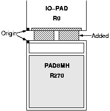
The bonding area to be used is called PAD6MH and can be found in the
library FSC0H_IO6 .
Place it, like in the figure, on the outside of an IOpad and fill the space
between the cells with metal to make a connection from the pad to the
bonding area.
Note that the origins of the cells are facing each other which will make
it easy to place the bonding area a fix distance from the IOpad.
Recommended distance are 5um from the IOpad and a spacing of 4um
between the bonding areas.
Design Rule Check
- The setup script for df2 will also set up the environment for some Design Rule Check (drc) by the product Assura.
- To run, click on Assura > Run DRC in the layout editor window. Make sure that the cell to be tested are the one chosen
- in the popup form. Run Directory is where Assura will write temporary and log files during checking. This can grow
- awfully big and might have to be moved into some temporary area with enough free space. Click OK to start.